Guess I'll use this thread as a scratch-pad for my thoughts.
I have been doing a lot of research into the benifits and characteristics of the 3 different types of clutch LSD.
The three different kinds are 1 way 1.5 way and 2 way.
1 way diffs increase lock only on acceleration, on decelleration they operate essentially as an open diff, there is some friction from the preload in the LSD but I believe this is minimal. The quaife diff operates in this method (using different technology)
1.5 way diffs act the same as a 1 way diff during acceleration but also lock the diff to some extent during deceleration, the factor for lock-up while decelerating is often 50% of the acceleration lock-up. The added benefit of having lockup while decelerating comes when under hard braking, it helps to ensure that one front wheel does not try to lock up before the other, this will allow the driver to get closer to the optimum braking. However, they can be a bit brutal on the steering, as the diff trys to lock the front wheels together the car wants to go straight, I believe this can be unwieldy in a street car especially with manual steering.
2-way diffs lock up equally as hard in both acceleration during acceleration and deceleration. These are usually used in drift cars where you want the back to step out when you hop off the gas.
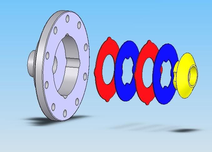
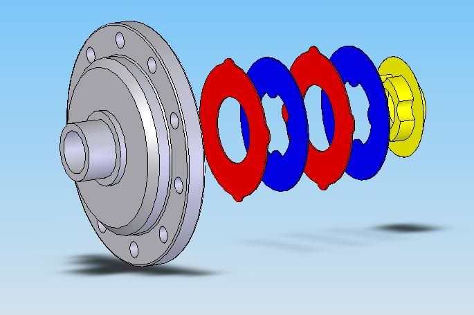
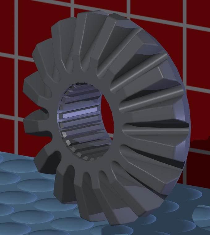
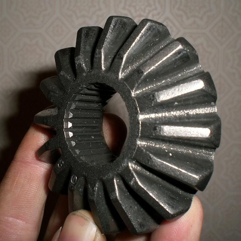
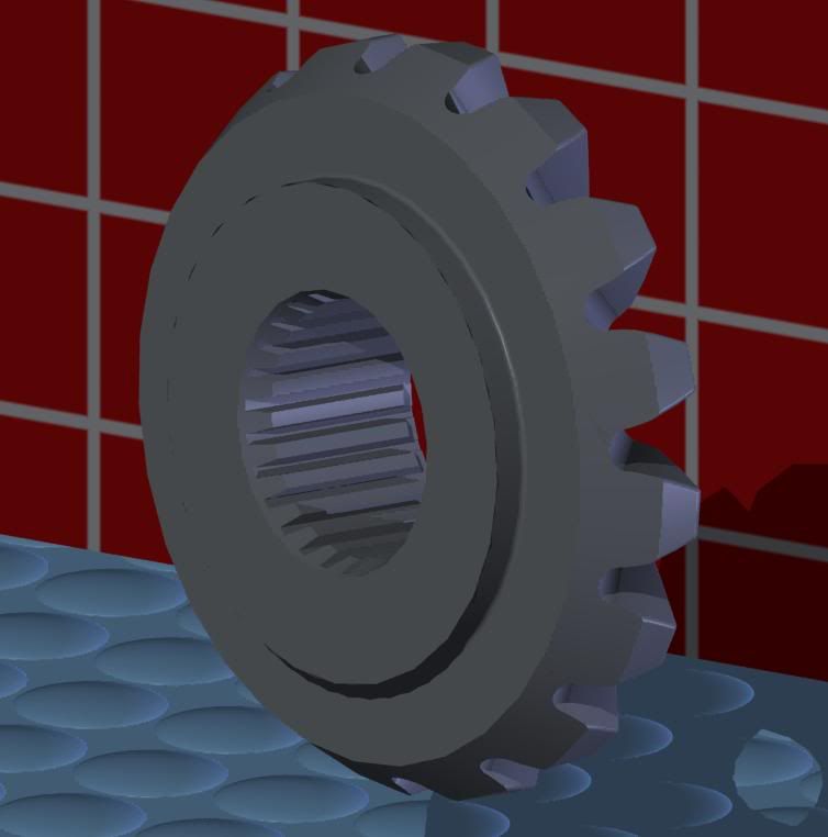
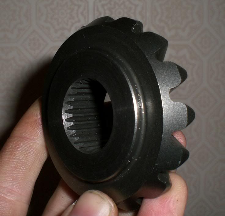
The lock-up characteristics are modified by changing the cam profiles on the pressure rings in the center of the diff.

This diagram shows the operation of a 2-way LSD, 1 way and 1.5 way are just a change of the angles in that squareish hole.

This is snaked from the kaaz site:
A Comparison of LSD
There are many brands and grades of LSD in today's market.
The OEM supplied LSD, standard and optional on many cars today are 2 pinions. This design has very low positive lock and it is designed to provide some sporty feel to the showroom cars. Because of the nature of this low lock design, it is just slightly more effective than not having one at all. Not a choice for true performance drivers.
A performance LSD should have at least 4 pinions. This is the design used for racing and rallies around the world. The positive lock ratio and linear lock characteristics are determined by a number of components. The cam profile, clutch plate quantity and size, initial torque of the preload springs and the lubricants.
A viscous type, torsen type and helical type are some of other designs used as OEM equipment or optional LSD unit. These designs are commonly used since they are less aggressive and easier to maintain than the clutch type racing LSD unit. In order to achieve the maximum traction control, most OEM performance divisions and aftermarket manufactures use the clutch type design for their LSD unit.
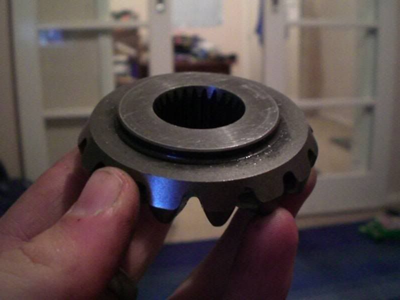
Clutch Plates:
Essentially teh more clutch plates you have the better. This is for several reasons.
-The more clutch plates you have the more friction they can generate, this friction is what locks your wheels together and performs the LSD function. You essentially want a fixed amount of friction available for your car to drive a certain way, there are two ways to get this friction, either by having a high preload from the springs in the diff, or by having lots of plates. The downside to having a high preload and fewer plates is that you get greater plate wear because the same amount of friction is spread over less area, you also get more sudden action when the highly loaded plates let go.
The mugen LSD for the 1st gen civic which I assume is very similar to the T2 one used 4 friction plates either side of the diff, 2 connected to the spider and two to the housing each side. This is probably suitable for all of our needs however more is better (if they fit!).
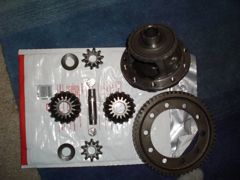
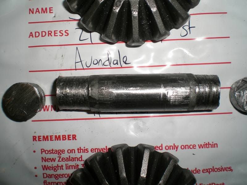
So, my plan is to try and design the diff to use 6 friciton plates per side, if this is unfeasible I will use 4, this should be fine as it was good enough for mugen! I intend to use the gears from a factory T2 diff. This will keep the cost and manufacturing time down hugely. The only downside is that I want to make a 4 pinion diff, this means I need the pinion gears from two diffs. This shouldn't be too bad If it turns out the ones from EW civics are the same, which I am fairly sure they are.
Anyway its my bed time, I shall continue this rant tomorrow