Custom Diff

Post whatever you like in here but try to keep it Honda City related!
User avatar
James
Moderator / Donating Member
Posts: 3092
Joined: Wed Apr 09, 2003 1:59 pm
Location: Putaruru
Contact:

Custom Diff

Postby James » Wed Jul 04, 2007 8:18 pm

I've decided to have a crack at making an LSD for myself. I have all the gear at uni and it looks like Ill be there for a while 'cause Im going to be doing postgrad. Hell Im gonna be in charge of the CNC mill next year :D

I have been heavily researching materials in the past couple of weeks and I have found some interesting information. It would appear the friction plates in clutch LSD's are commonly 1035 low carbon steel with surface hardeneing presumably for wear resistance. They get these surfaces to have friction against each other using special oils.

For the housing Im going to initially use mild steel, its easy to machine and should be strong enough. So that means my material costs will be like $50, machining time and design time is going to be the main expenses both of which I should be able to get free for the most part :D

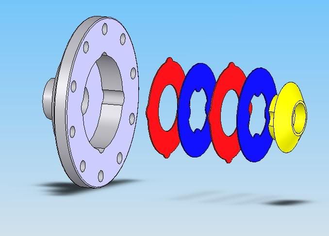
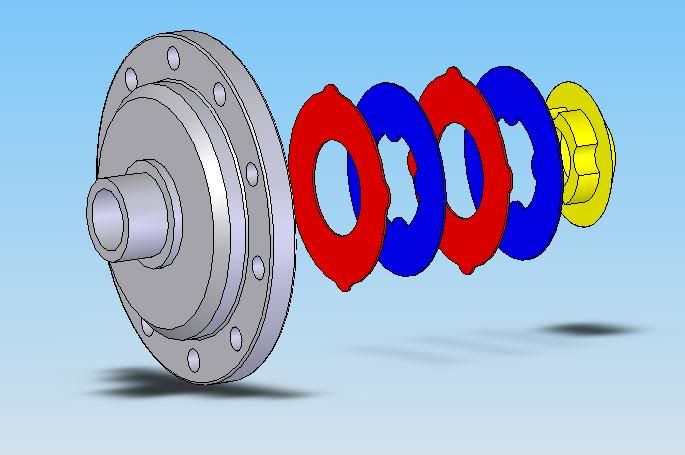
Here are some preliminary pics from Cadding of the LSD. I have already done a fairly accurate CAD model of the factory one, now just making an LSD version. Obvisouly some gear teeth and splines missing.

Image

Image

User avatar
3GCVC
Forum Addict
Posts: 391
Joined: Sun May 27, 2007 5:17 pm
Contact:

Postby 3GCVC » Thu Jul 05, 2007 7:26 am

will you be making more than one?

sin-city_turbo
Forum Regular
Posts: 75
Joined: Tue Jan 31, 2006 11:08 am
Location: NZ

Postby sin-city_turbo » Thu Jul 05, 2007 11:40 am

yeah man, you could make a Gazzillion dollars from making LSD's for city turbo's!

User avatar
James
Moderator / Donating Member
Posts: 3092
Joined: Wed Apr 09, 2003 1:59 pm
Location: Putaruru
Contact:

Postby James » Thu Jul 05, 2007 1:47 pm

3GCVC wrote:will you be making more than one?


I could probably be persuaded ;)

Will be making one as a test to start with. But when I get the friction plates laser cut I will get a few extras cut so if it all works I can make another couple fairly quickly.

For the plan I have at the moment It is probably going to take 2, T2 or 3g civic diffs to make 1 LSD, because I am using the pinion gears out of them. I am making a super strong 4 pinion design so the pinion shafts shouldn't break, a common problem with lesser quality LSD's. However I may end up making some custom pinion gears in which case it will only take 1 T2 or 3g diff to make each LSD using only the spider gears from them.

Hyperblade
Moderator / Donating Member
Posts: 1217
Joined: Sat Feb 21, 2004 9:31 am
Location: Christchurch, New Zealand

Postby Hyperblade » Thu Jul 05, 2007 3:55 pm

I'm reasonably keen depending on price (T2), keep us posted :)

User avatar
James
Moderator / Donating Member
Posts: 3092
Joined: Wed Apr 09, 2003 1:59 pm
Location: Putaruru
Contact:

Postby James » Thu Jul 05, 2007 5:32 pm

Yeah will do. This will be as close to a mugen replica diff as I can get, without actually seeing one apart :P

I have a good picture of a diassembled 1st gen civic mugen LSD so thats part of my design cues.

User avatar
James
Moderator / Donating Member
Posts: 3092
Joined: Wed Apr 09, 2003 1:59 pm
Location: Putaruru
Contact:

Postby James » Tue Jul 10, 2007 8:57 pm

Guess I'll use this thread as a scratch-pad for my thoughts.

I have been doing a lot of research into the benifits and characteristics of the 3 different types of clutch LSD.

The three different kinds are 1 way 1.5 way and 2 way.

1 way diffs increase lock only on acceleration, on decelleration they operate essentially as an open diff, there is some friction from the preload in the LSD but I believe this is minimal. The quaife diff operates in this method (using different technology)

1.5 way diffs act the same as a 1 way diff during acceleration but also lock the diff to some extent during deceleration, the factor for lock-up while decelerating is often 50% of the acceleration lock-up. The added benefit of having lockup while decelerating comes when under hard braking, it helps to ensure that one front wheel does not try to lock up before the other, this will allow the driver to get closer to the optimum braking. However, they can be a bit brutal on the steering, as the diff trys to lock the front wheels together the car wants to go straight, I believe this can be unwieldy in a street car especially with manual steering.

2-way diffs lock up equally as hard in both acceleration during acceleration and deceleration. These are usually used in drift cars where you want the back to step out when you hop off the gas.

The lock-up characteristics are modified by changing the cam profiles on the pressure rings in the center of the diff.

Image

This diagram shows the operation of a 2-way LSD, 1 way and 1.5 way are just a change of the angles in that squareish hole.

Image

This is snaked from the kaaz site:

A Comparison of LSD

There are many brands and grades of LSD in today's market.

The OEM supplied LSD, standard and optional on many cars today are 2 pinions. This design has very low positive lock and it is designed to provide some sporty feel to the showroom cars. Because of the nature of this low lock design, it is just slightly more effective than not having one at all. Not a choice for true performance drivers.

A performance LSD should have at least 4 pinions. This is the design used for racing and rallies around the world. The positive lock ratio and linear lock characteristics are determined by a number of components. The cam profile, clutch plate quantity and size, initial torque of the preload springs and the lubricants.

A viscous type, torsen type and helical type are some of other designs used as OEM equipment or optional LSD unit. These designs are commonly used since they are less aggressive and easier to maintain than the clutch type racing LSD unit. In order to achieve the maximum traction control, most OEM performance divisions and aftermarket manufactures use the clutch type design for their LSD unit.


Clutch Plates:

Essentially teh more clutch plates you have the better. This is for several reasons.

-The more clutch plates you have the more friction they can generate, this friction is what locks your wheels together and performs the LSD function. You essentially want a fixed amount of friction available for your car to drive a certain way, there are two ways to get this friction, either by having a high preload from the springs in the diff, or by having lots of plates. The downside to having a high preload and fewer plates is that you get greater plate wear because the same amount of friction is spread over less area, you also get more sudden action when the highly loaded plates let go.

The mugen LSD for the 1st gen civic which I assume is very similar to the T2 one used 4 friction plates either side of the diff, 2 connected to the spider and two to the housing each side. This is probably suitable for all of our needs however more is better (if they fit!).

So, my plan is to try and design the diff to use 6 friciton plates per side, if this is unfeasible I will use 4, this should be fine as it was good enough for mugen! I intend to use the gears from a factory T2 diff. This will keep the cost and manufacturing time down hugely. The only downside is that I want to make a 4 pinion diff, this means I need the pinion gears from two diffs. This shouldn't be too bad If it turns out the ones from EW civics are the same, which I am fairly sure they are.

Anyway its my bed time, I shall continue this rant tomorrow :D

User avatar
3GCVC
Forum Addict
Posts: 391
Joined: Sun May 27, 2007 5:17 pm
Contact:

Postby 3GCVC » Wed Jul 11, 2007 6:26 pm

if you want any 3G civic diffs i have a box or two i could possibly take apart for parts only if you want to give me a good on one of the units though. lol

User avatar
James
Moderator / Donating Member
Posts: 3092
Joined: Wed Apr 09, 2003 1:59 pm
Location: Putaruru
Contact:

Postby James » Thu Jul 12, 2007 6:06 am

I am in need of a diff or two at the moment, the one I intended to use as my development is pretty stuffed, the pinion shaft is worn down like a mm.

If you could take one out and we will make some measurements to see if they are the same? And yeah, if you help me in this development stage I will certainly be happy to give you a good hookup on a diff.

User avatar
3GCVC
Forum Addict
Posts: 391
Joined: Sun May 27, 2007 5:17 pm
Contact:

Postby 3GCVC » Fri Jul 13, 2007 10:01 am

i have an automatic box im happy to pull apart and will be doing soon. dont know about my spare manual box but i may be able to take one apart without breaking it then just put the LSD back into it.

User avatar
James
Moderator / Donating Member
Posts: 3092
Joined: Wed Apr 09, 2003 1:59 pm
Location: Putaruru
Contact:

Postby James » Fri Jul 13, 2007 10:50 am

Sweet, it will be interesting to find if the auto diff is the same, could be an easier option for non-raped diffs.

User avatar
James
Moderator / Donating Member
Posts: 3092
Joined: Wed Apr 09, 2003 1:59 pm
Location: Putaruru
Contact:

Postby James » Fri Jul 13, 2007 4:31 pm

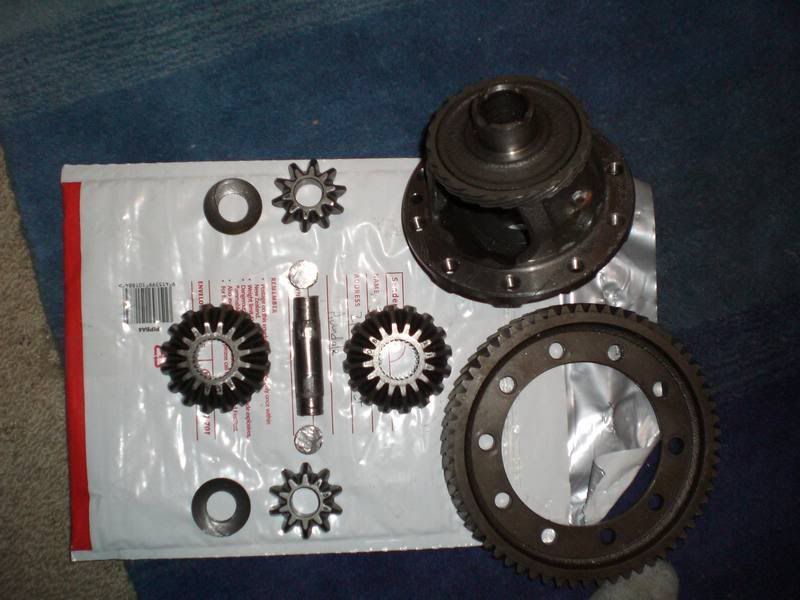
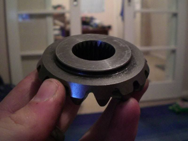
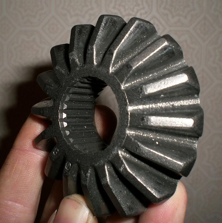
OK so after like fricken 5 hours of beating at my spare diff with hammers and shit I finally got it apart!

First of all it took me like 2 hours of pissing about and drilling and beating to get the roll pin that holes the pinion shaft in, out. My recommendation to anyone trying is give it 5 minutes with a 4mm pin punch then take to it with a drill.

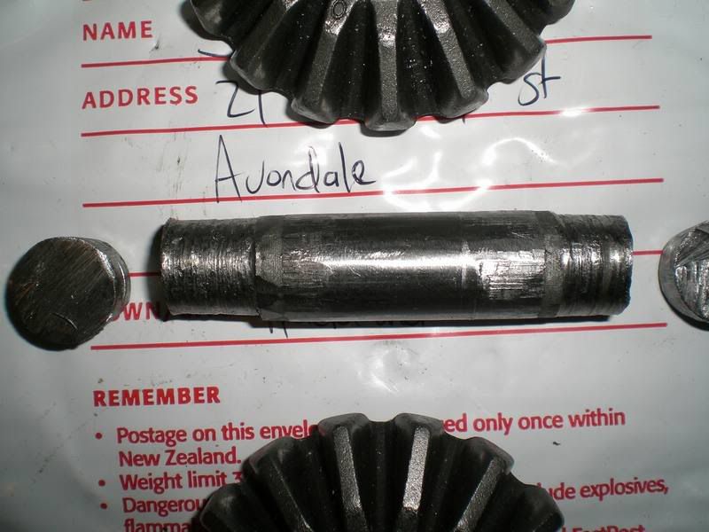
The pinion gears had worn into the shaft heaps which ment that there were heaps of burrs and shit on it which made it practically impossible to drive it back through the gears, this is why I need to get my hands on a couple of other T2 diffs (hopefully without fuckt pinions!).

In the end I had to bash the pinion shaft out as far as I could then hacksaw about 10mm off the end. I then had to stick a file through the guts and file down the burrs on the shaft. Then bashed it through the other way and cut about 10mm off the other end. *then* bashed it back through *again* and cut off about 5mm. It was then short enough to spin the gears around in the housing and remove them.

Image

Image

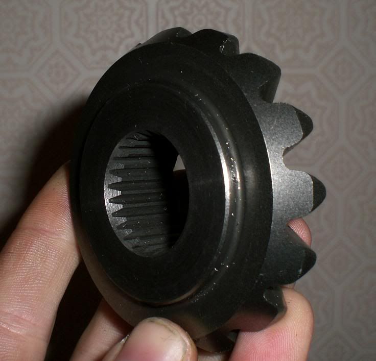
Anyway, I will illustrate my plan for modifying the spider gears.

Image

I am going to extend the existing ridge on the back of the gear another 4-5mm, I will also add key's to spline half the friction plate on with. I will do this in the cnc mill whilst craftily holding it with some contraption. :D

User avatar
James
Moderator / Donating Member
Posts: 3092
Joined: Wed Apr 09, 2003 1:59 pm
Location: Putaruru
Contact:

Postby James » Fri Jul 13, 2007 7:33 pm

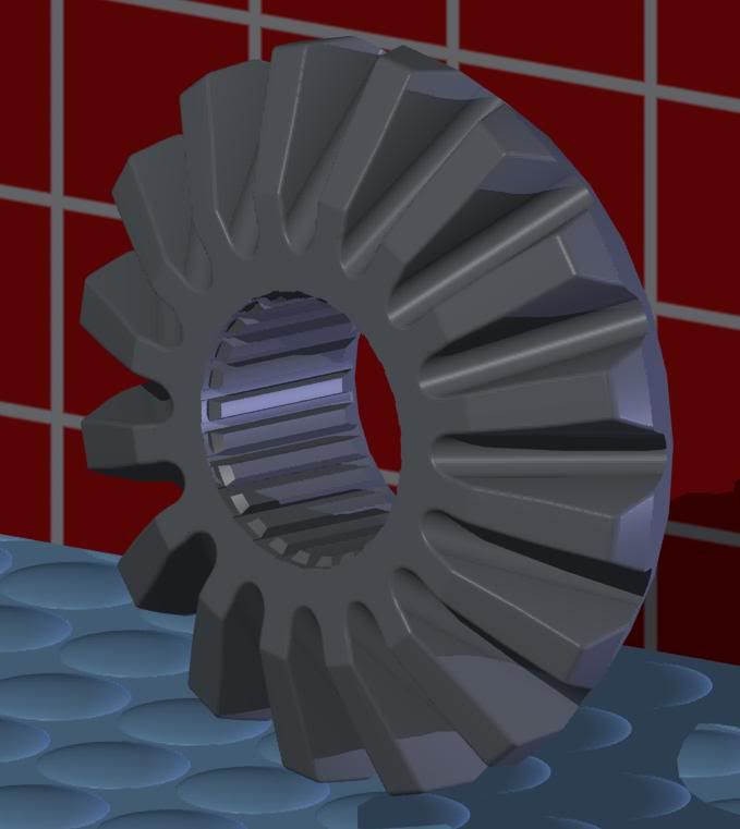
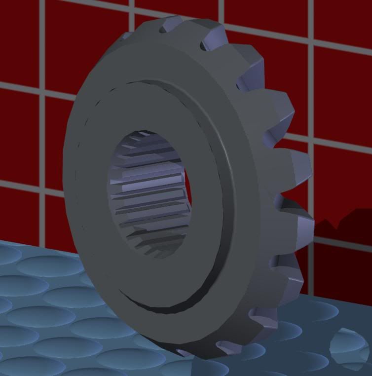
Just finished modelling the factory spider gear, its pretty accurate. Here is some renderings of it.

Image

Image

Image

Image

Hyperblade
Moderator / Donating Member
Posts: 1217
Joined: Sat Feb 21, 2004 9:31 am
Location: Christchurch, New Zealand

Postby Hyperblade » Sat Jul 14, 2007 9:08 am

Looking good!

User avatar
3GCVC
Forum Addict
Posts: 391
Joined: Sun May 27, 2007 5:17 pm
Contact:

Postby 3GCVC » Mon Jul 23, 2007 10:43 am

hows this comming along i still need to get you a couple of diffs, hopefully this week sometime i might be able to get them out.


Return to “General”

Who is online

Users browsing this forum: No registered users and 116 guests