I can't remember much about that RPM stuff, I might have some notes somewhere so I will check that out.
I have a socketed T2 ECU that you could borrow if you want, its got an EPROM in it at the moment with the boost cut moved to 16.5psi. I have been waiting for years now to have my car running again so I can do Hex trace with an Ostrich!! You're beating me to it!! I'm going to have lots of spare time in the next month or so, so I might get back into commentig that code.
You should be able to commit code to the project now, if you need to add files and can't or whatever let me know and I'll bump up your permissions.
City T2 ECU Reverse Engineering Mk2
-
James

- Moderator / Donating Member
- Posts: 3092
- Joined: Wed Apr 09, 2003 1:59 pm
- Location: Putaruru
- Contact:
http://www.oshonsoft.com/8085.html
Thats what I used to Dissasemble and Assemble my programs, it seems to work pretty well, although it has its quirks. I used Notepad++ for all my editing.
Yeah its a pretty straight forward ECU to socket, I would cut the legs off the chip and desolder those individually as the tracks are pretty fragile.

-
bmgjet

- Donating Member
- Posts: 220
- Joined: Fri Dec 03, 2010 3:23 pm
- Location: New Zealand New Plymouth
- Contact:
Thanks for the ECU's 3GCVC.
---
Opened up the T1 ecu and it has a visible differences.
Ill upload the pictures and PCB scan of the T1 and T2 ecu to the googlecode project.
---
Got started on socketing the T2 ecu and its being a real pain since the chip is glued down to the PCB so have given up for the night so I dont tare any traces trying to force it. Will attack it tomorrow with a heat gun so the glue is loosened up.
---
Attacked it with the GF hair drying and that softened the glue enough to pull the chip out.
Go the sock and emulator installed ready to do some map tracing tomorrow.
Will do a Wiki write up on how to chip T2 ecu on the GC project.
---
Opened up the T1 ecu and it has a visible differences.
Ill upload the pictures and PCB scan of the T1 and T2 ecu to the googlecode project.
---
Got started on socketing the T2 ecu and its being a real pain since the chip is glued down to the PCB so have given up for the night so I dont tare any traces trying to force it. Will attack it tomorrow with a heat gun so the glue is loosened up.
---
Attacked it with the GF hair drying and that softened the glue enough to pull the chip out.
Go the sock and emulator installed ready to do some map tracing tomorrow.
Will do a Wiki write up on how to chip T2 ecu on the GC project.
-
James
- Moderator / Donating Member
- Posts: 3092
- Joined: Wed Apr 09, 2003 1:59 pm
- Location: Putaruru
- Contact:
I think I used Isopropyl alcohol to get that resin stuff off, it's a bit of a pain.
I have drawn a significant portion of the T2 ecu as a schematic in Altium Designer if you were interested, it helps when you track down how a bit of IO is working and you want to know what signal it's reading or something. I have a T2 ecu with everything desoldered from it both sides so you can trace every track. I can probably scan that if I can find it.
Did you noticed the blank spot for a connector in one corner of the board? That's for the parallel diagnostics connector, it would be interesting to stick a micro on there and see what the data that comes out looks like.
-
bmgjet
- Donating Member
- Posts: 220
- Joined: Fri Dec 03, 2010 3:23 pm
- Location: New Zealand New Plymouth
- Contact:
Yup noticed that.
CN3
With OBD0 and OBD1 CN2/3 are used for data-logging so I guessed it would be sort of the same.
I had a look at the schematics on the GC project page and the ECU is quite simple compared to more modern ones. Altho it has a lot more chips but I guess back then you needed a chip for each function instead of having ones that can do multiple things.
Im going to throw the T2_16.5 map on the ostrich and take it for a drive to make sure the sockets in there properly.
-
James
- Moderator / Donating Member
- Posts: 3092
- Joined: Wed Apr 09, 2003 1:59 pm
- Location: Putaruru
- Contact:
Sweet, sounds good.
Yeah the silicon from a lot of those chips is now incorporated straight into the microprocessor.
It has:
MSM81c55 - external ram an I/O ports and timer
38128 External ROM
8253 Timer
5114 4-bit ram
4013 Flip Flop
4017 Decade Counter
4019 Quad And/Or Selector
4023 3 input NAND
4027 Flip Flop
4028 Binary Coded Decimal Decoder
4051 Analog Multiplexer
4071 OR Gate
74138 De Muliplexer
74374 Latch
2903 Op-Amp
5204 8 Bit Analog to Digital Converter
6203 Multiply and Divide Chip
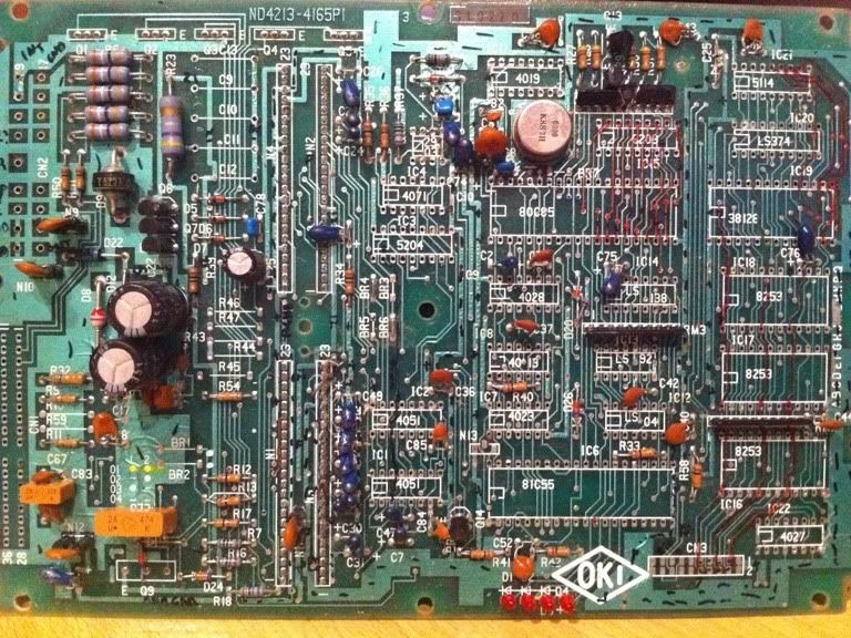
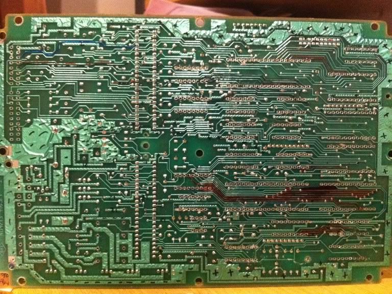
Note quite all the components but enough to trace most of the tracks. I will do proper scans this weekend.
Yeah the silicon from a lot of those chips is now incorporated straight into the microprocessor.
It has:
MSM81c55 - external ram an I/O ports and timer
38128 External ROM
8253 Timer
5114 4-bit ram
4013 Flip Flop
4017 Decade Counter
4019 Quad And/Or Selector
4023 3 input NAND
4027 Flip Flop
4028 Binary Coded Decimal Decoder
4051 Analog Multiplexer
4071 OR Gate
74138 De Muliplexer
74374 Latch
2903 Op-Amp
5204 8 Bit Analog to Digital Converter
6203 Multiply and Divide Chip
Note quite all the components but enough to trace most of the tracks. I will do proper scans this weekend.
-
James
- Moderator / Donating Member
- Posts: 3092
- Joined: Wed Apr 09, 2003 1:59 pm
- Location: Putaruru
- Contact:
bmgjet wrote:Must of been a mission de-soldering all those.
Did you cut the legs or de-solder them intact?
Its amazing to see how ECU's have progressed. But just amazing how complex these ecus are for early 80s.
On another note, Drove home on the 16.5psi map with out a problem.
Yeah it took a while but I did it at uni we had a desoldering tool, basically a hollow soldering iron with a vacuum pump. I probably cut the legs on them, makes it easier, just need pointy side cutters.
That's awesome that 16.5psi map worked, means I got it right all those years ago
I'll make you an owner of the project, then you'll have the same abilities as me, just use your power for good only
It is pretty impressive how complicated these ecus are, especially given they were hondas first ever ecu. I think they took a lot of tech from their F1 development for them. They stayed very similar for many years, until the likes of obd2 really.
-
bmgjet
- Donating Member
- Posts: 220
- Joined: Fri Dec 03, 2010 3:23 pm
- Location: New Zealand New Plymouth
- Contact:
Didnt take it up to fuel cut so cant comment on if thats working.
But it drives on the map fine.
Will only do things to improve the project.
Will start with all the small things first before I get into the ASM.
Hondas always been good like that using there racing tech on street cars. Too bad they no longer have a F1 team.
But it drives on the map fine.
Will only do things to improve the project.
Will start with all the small things first before I get into the ASM.
Hondas always been good like that using there racing tech on street cars. Too bad they no longer have a F1 team.
-
James
- Moderator / Donating Member
- Posts: 3092
- Joined: Wed Apr 09, 2003 1:59 pm
- Location: Putaruru
- Contact:
Thats very interesting.
It might have been that it was throwing an error, because I didn't change anything other than the one boost cut value. Would be interesting to try it again. Try with 16.5psi bin, if it doesnt start try with stock bin, turn off straight away and try 16.5psi bin again. Could also check ECU for LEDs while trying to start it.
It might have been that it was throwing an error, because I didn't change anything other than the one boost cut value. Would be interesting to try it again. Try with 16.5psi bin, if it doesnt start try with stock bin, turn off straight away and try 16.5psi bin again. Could also check ECU for LEDs while trying to start it.
-
bmgjet
- Donating Member
- Posts: 220
- Joined: Fri Dec 03, 2010 3:23 pm
- Location: New Zealand New Plymouth
- Contact:
Were no error LEDs. Started up on stock T2 bin after a few turn overs. The 16.5psi bin wont start it up at all now, Just floods it.
No Errors and PGMFI light comes on while fuel pump primes then goes out like normal.
Going to try starting it with stock T2.bin then update it to 16.5psi one while its running. Strange that it worked last night.
No Errors and PGMFI light comes on while fuel pump primes then goes out like normal.
Going to try starting it with stock T2.bin then update it to 16.5psi one while its running. Strange that it worked last night.
Who is online
Users browsing this forum: No registered users and 202 guests